
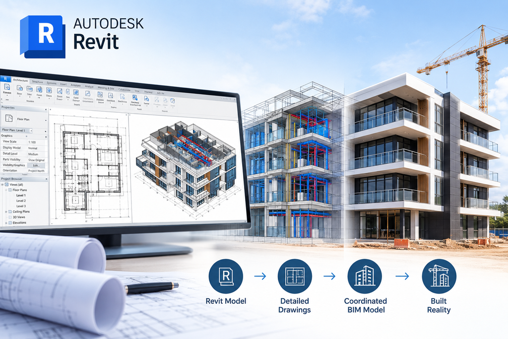
Architectural drawings make a promise about a building. The wall goes here. The door swings there. The slab sits at this level. However, the contractor arrives with a tape measure and finds the corridor is 40 mm narrower than the sheet says. Meanwhile, the ceiling void sits nowhere near where anyone expected it.
Revit BIM architecture is meant to close that gap. It only works, though, when the model comes from what is really on the ground. This article starts with the basics. Then it follows the path from measured site data to drawings that match what is actually built.
What Revit BIM Architecture Actually Means
Revit is modeling software from Autodesk. BIM stands for building information modeling. Together, they describe a building as a digital model made of real components. Separate drawings are no longer the starting point. The architectural side covers what people see and use. That means walls, floors, roofs, ceilings, doors, windows and stairs. It also covers the rooms they form. Structure and building services usually sit in their own models alongside it.
The key word is information. A wall in the model is not two parallel lines. Instead, it carries a height, a thickness, a material and a level. For example, you can ask for every door on the second floor, and the model lists them with their sizes.
How a Revit Model Differs From a Set of CAD Drawings
In CAD, the plan, section and elevation are drawn one at a time. If a window moves, someone must move it in every view. They must also update the schedule. Sooner or later, one change gets missed. As a result, the drawings begin to contradict each other. Revit BIM architecture works differently. Every view comes from one model. Move the window once, and all views follow. Therefore, a whole class of small errors disappears.
CAD has not gone away, though. Many contractors still work in it. For that reason, a good Revit model can also be issued as CAD sheets when needed. Our team handles this kind of modeling for projects across Abu Dhabi.
What an Architectural Model Contains: Walls, Floors, Doors and Data
Every Revit BIM architecture model starts with levels and grids. Levels set the floor heights. Grids set the wall and column lines. Everything else is placed against them, so an error here runs through the whole model. Next come the building elements. These include walls, floors, roofs, ceilings, stairs and openings. Doors and windows come from families, which are reusable components with adjustable sizes. Rooms are added with names, numbers and areas. As a result, the model can also produce area schedules and finish lists.
Existing buildings need one more feature, which is phasing. Revit can mark each element as existing, demolished or new. Therefore, one model can show a renovation clearly, with the old walls and the new ones on the same sheet. The level of detail depends on the job. A model for early planning can stay simple. A renovation model needs accurate wall thicknesses, opening sizes and floor levels. Builders will cut, fit and order materials from those numbers, so agree the detail before modeling starts.
Why Drawings and the Finished Building Rarely Agree
Design drawings show intent. They record what the designer planned on the day of issue. After that, buildings change. A beam is lowered to clear a duct. On another floor, a partition shifts. Elsewhere, a slab is poured slightly high. The change is agreed on the spot, but it never returns to the drawing. Older buildings add a second problem. Many have no reliable drawings. Others have drawings from the original design, made before years of alterations. A wall that looks plumb on paper may lean. Likewise, a floor shown as level may fall several centimetres across a room.
A model built from those drawings repeats the mistake. Worse, it does so in a more convincing format. Because a tidy 3D model feels trustworthy, errors inside it are harder to spot. The fix is to start from measurement instead of old paper.
Bringing Survey and Scan Measurements Into Revit
Measured data enters the model in two ways. First, a site survey fixes where the building sits and at what level. Revit then uses shared coordinates, so the model lands in the right place. Its levels follow the project datum instead of a guess. Second, scanning records the building as a point cloud. This is a cloud of millions of measured points that show the real geometry. The modeler places the cloud in Revit and builds each wall, floor and opening against it. As a result, every element traces back to a measurement, not an assumption. The full workflow from scan to model is explained step by step elsewhere on our site. One rule matters most here. In Revit BIM architecture work, the model should follow the scan. Where the two disagree, find out why before changing anything.
Checking the Model Against the Site Before Drawings Are Issued
A model can look neat and still be wrong. So it needs a check before anything is issued. Ideally, someone other than the modeler does it. Modelers tend to see what they meant to draw. Start with a short list of key dimensions. These might be room widths, ceiling heights, door openings and floor levels at several points. Compare each one with the scan or the site. Then record the difference in a simple table.
Next, compare the differences with the accuracy agreed for the job. If they fall inside it, the model passes. If not, trace the cause and fix it. Sometimes the cause is a hidden wall finish or a misplaced level. Finally, mark what could not be measured. Areas behind finishes, above ceilings or inside locked rooms are often modeled from assumption. The drawings should say so. A note that an area is assumed helps a contractor far more than a clean line that looks certain.
From Revit Model to Drawings a Contractor Can Build From
Once the model is checked, the Revit BIM architecture drawings come straight from it. These include plans, sections, elevations, schedules and detail views. Each sits on a sheet with the dimensions and notes a builder needs. Because every sheet comes from one model, the plan and the section agree by construction.
A few habits make sheets easier to use on site. First, dimension the elements that matter for building, not just those that are easy to tag. Second, keep annotation consistent from sheet to sheet. Third, control revisions with clouds and a revision table, so the site team knows which issue is current. Finally, issue sheets in the formats the project needs, usually PDF and, where required, CAD. Later changes follow the same path. Update the model first. Then reissue the sheets. In this way, the drawings and the building stay in step.
Conclusion
Revit BIM architecture is not about a nicer 3D picture. Its value lies in drawings you can trust, and that trust comes from measurement. So start with survey and scan data. Build the model against it. Check the model on site, and only then issue the sheets.
Done in this order, the drawings match what is actually built. Therefore, the rework that follows a mismatch never happens. If you need reliable modeling for an existing building, contact our team with your project details.
FAQs
1. What is Revit BIM architecture?
It is the use of Autodesk Revit to build the architectural part of a building as a 3D model full of data. Plans, sections, elevations and schedules then come directly from that model.
2. Can Revit drawings be made for a building that has no drawings?
Yes. A laser scan or site survey captures the building as it stands. The model and drawings are then built from that data.
3. How accurate are drawings made from scan data?
That depends on how the scan was captured and on the tolerance agreed for the job. Set the tolerance at the start, and check the finished model against the scan.
4. Do I still need CAD drawings if I have a Revit model?
Not always. The model produces the sheets, and these can be exported to CAD for anyone who still works in that format.
5. What should I share before modeling starts?Share any existing drawings and the purpose of the model. Also share the level of detail you need, the project coordinate system and the file formats require