
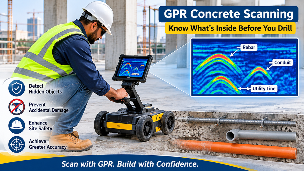
Two technicians can scan the same slab with the same machine and report different results. The difference lies in how they plan the scan, how they set up the instrument and how they read the data. Understanding that craft helps you judge a result before anyone drills.
This article looks inside GPR concrete scanning. It covers the equipment, the scan layout, the interpretation of the signal and the reporting you should expect. For an overview of why you need a scan, read the guide to concrete scanning in Abu Dhabi.
What Is GPR Concrete Scanning?
GPR concrete scanning uses ground penetrating radar to look inside concrete without damaging it. A small antenna sends radar pulses into the slab or wall and records the echoes that return. Steel, plastic and voids each reflect the signal in a different way, so the echoes reveal what sits inside.
GPR Equipment and Antenna Frequency Selection
A concrete GPR unit has an antenna, a control unit and a display, and technicians usually push it across the surface on wheels. The antenna frequency matters most.
Concrete scanners commonly use antennas in the range of roughly 1.5 to 2.6 GHz. A higher frequency gives finer detail and separates closely spaced bars, but it loses strength quickly with depth. A lower frequency reaches deeper but blurs small targets. For a thin slab with dense reinforcement, a high frequency suits best. For a thick raft or a deep element, a lower frequency may be necessary.
Scan Planning: Grids, Directions and Surface Preparation
Good data starts before the first pass. The technician reviews the drawings, marks a grid on the surface and clears debris, because the antenna needs steady contact with the concrete.
Direction matters as well. A radar scan sees a linear object best when the antenna crosses it at a right angle. The technician therefore scans in two perpendicular directions. This reveals both layers of a reinforcing mesh and any conduit running across it. Wide gaps between scan lines leave blind spots, so the grid spacing should match the size of the target. Finally, allow new concrete to cure, since fresh concrete holds water and weakens the signal.
How Radar Signals Become Images: Reading the Scan
The screen shows a cross-section called a radargram. Each pulse becomes a vertical trace, and the traces line up side by side as the antenna moves.A small round target, such as a bar or a pipe, spreads the echo into a curved arc. The top of the arc marks the target’s position and depth.
Flat, continuous lines show layers, such as the bottom of the slab. Because steel reflects almost all the signal, it also hides anything directly beneath it. Many systems also build a plan view from the grid data, which displays the layout of bars and conduits at a chosen depth. This view helps the technician mark the surface accurately.
Depth Calibration and Measurement Accuracy
The instrument measures time, not depth. It converts time to depth using the speed of the radar wave in the concrete, and that speed changes with moisture, mix and age.The technician therefore calibrates on site. A known depth, such as the slab thickness at an exposed edge or a core hole, gives a reference.
The software then adjusts the velocity so the depths match. Without calibration, the depth readings can be off by a noticeable margin. Ask the provider how they calibrated and how they checked the equipment. In the UAE, the Ministry of Industry and Advanced Technology oversees standards and metrology, which is a useful starting point for questions about equipment checks.
Identifying Rebar, Conduits and Post-Tension Cables in the Data
Each target leaves its own pattern, and the experienced eye reads them together.
- Rebar appears as a regular row of arcs at a fairly constant depth.
- Metal conduit gives a strong arc, often with wider spacing than the bars.
- Plastic conduit gives a weaker arc, and the technician confirms it with scans in both directions.
- Post-tension cables also appear as arcs, but their depth changes along the length of the slab, which distinguishes them from straight bars.
- Voids change the character of the signal in the area around them.
Where the data is unclear, the technician should say so. Never treat an uncertain area as empty. A structural engineer should approve any cut near a suspected post-tension cable, and the structural drawings help confirm where the designer placed them.
Recording and Presenting GPR Concrete Scanning Results
Technicians mark the findings on the concrete with paint or chalk, so the drilling crew sees them directly. They also record the work. A solid report holds photographs of the marked surface, a plan showing the scan lines and findings, sample radargrams, the calibration method and a note of any uncertain zones.
The office team can turn the plan into a drawing with a CAD service. Teams that plan ahead include scanning in the pre-construction survey, and projects with buried services nearby also benefit from a utility survey. Before work begins, confirm the permits and approvals with the Department of Municipalities and Transport.
Conclusion
GPR concrete scanning delivers dependable results when the technician chooses the right antenna, plans the grid, calibrates the depth and reads the data with care. Ask your provider to explain these steps, and expect a report that states its limits. With that evidence in hand, your crew can drill and cut with confidence.
Frequently Asked Questions
What is GPR concrete scanning?
It is a non-destructive method that uses radar pulses to locate rebar, conduits, cables and voids inside concrete.
Which antenna frequency is best for concrete?
Concrete scanners commonly use high frequencies, roughly 1.5 to 2.6 GHz. Lower frequencies suit thicker elements.
Why does the technician scan in two directions?
Radar sees a linear target best when it crosses it at a right angle, so two directions reveal the whole layout.
How accurate are GPR depth readings?
Accuracy depends on calibration. The technician checks the depth against a known reference before reporting.
Can GPR miss something in concrete?
Yes. Dense steel can hide objects beneath it, and plastic gives a weak signal. A good technician reports these limits.